PRINTING & OUTPUT
Printing
3D Printing is enabled via the Print command on the File Menu and configured via the Printer Setup command.
If either of these conditions is not met for your printer then you will get an error when you try to print. In such cases you might consider taking a screen grab manually (ALT+PRINTSCREEN) or using the export command as described below.
Embed 3D Models
If your project contains STEP/IGES files that you've imported and you want to share or use the project on another computer then you most likely want to carry all the STEP/IGES files with you. Proteus can embed all of the relevant files for you via the Embed MCAD Models command on the File Menu in the 3D Viewer. This will of course make the resulting project file size considerably larger.
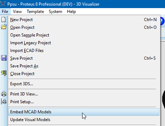
Embed the MCAD models used in this project into the project file via this menu option.
The Embed MCAD Models is a toggle and can be turned on or off per project. It defaults to OFF on a new project due to the huge difference enabling it will make to the size of the project file.
How it works
When the option is selected all of the 3D models for the components are stored inside the PDSPRJ file for the project. When the project is opened all of these files are extracted into a temporary directory and used for the 3D Visualization of the project. They are not copied across automatically into the MCAD directory of the computer in case a different file with the same name already exists there.
If you want the STEP/IGES files to be stored in the MCAD directory of the computer for later use then you need to select the parts on the layout and use Make Package to store the footprints into the libraries on the computer. This tells Proteus that you want the part and it's associated MCAD file to be stored on the PC and the software will take care of copying the 3D file across into your MCAD directory.
In summary, after embedding the 3D models the project file can be shared without worry about overriding files on other computers. If you want to store the 3D model files on other computers then use Make Package on the parts in the layout.
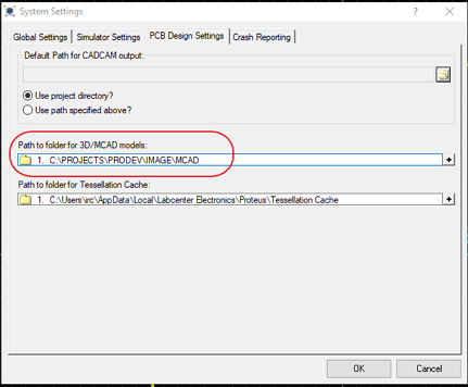
The location of the Permanent MCAD Model storage is set via System Menu - System Settings
MCAD Output
Export of the board for data exchange with MCAD software such as Solidworks, PTC or Autodesk normally takes place via the STEP or IGES file formats. These options are all available from the Output Menu in the ARES PCB Layout module.

M-CAD Data Exchange Options.
As with the 3D Viewer itself, these export options form part of the Advanced Feature Set and are enabled on PCB Design Level 2 and higher.
Do note that export of a STEP assembly is very computational intensive and, even for a modest board, several minutes processing time is not unusual. Progress will be reported in the log but it is often a good time to switch the kettle on and make a cup of coffee.
Export Rules
- The PCB board is exported.
- All holes on the board are exported.
- For each footprint on the board the MCAD model is exported.
- If no MCAD model exists a basic extrusion is exported and coloured red.
- The part reference information is exported.
- Tracks, silkscreen and other objects are not exported.
It is important to understand that visual models (3DS files) are not exported in a STEP or IGES file format as they are a collection of triangles rather than an object. For M-CAD export you must have a model in the M-CAD tab of the dialogue form.
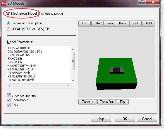
You must have either a geometric description or a STEP file on this tab to export a model in the STEP or IGES file.
Graphical Output
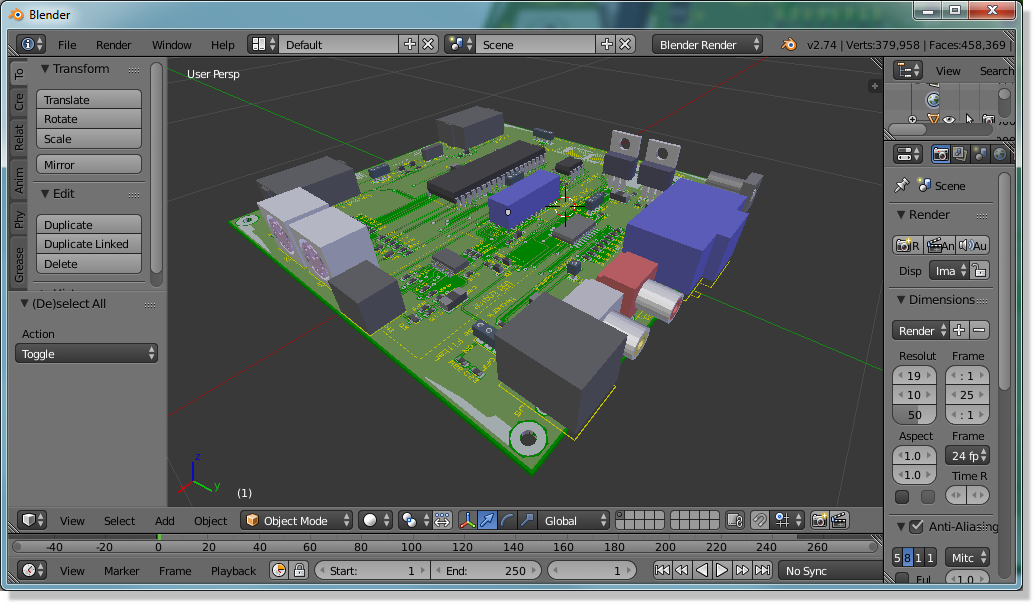
Graphical output takes place from the Export 3DS command on the File Menu of the 3D Viewer module. The difference here is that everything you see on the board is exported (silk, traces, copper, mask,, zones, objects, holes, board ,etc..) and the resulting file may therefore be very large.
It is very unlikely that the resulting output file will be of use in an M-CAD environment but it is nonetheless the most complete visualisation output available.